For context, this post is to explain a recent Instagram reel (https://www.instagram.com/p/C5BqIWzt5Dt/). As ever, familiarity with some existing origami design terminology will be helpful for understanding this post. (If you don’t have it, then read Origami Design Secrets…)

Compliments from the master
I first met Robert Lang when I was 12 at the BOS 40th anniversary convention. Paul Hanson set up a quick meeting since he knew Lang was my idea of origami royalty. (Let me take a moment to thank for all that Paul has done both for the British Origami Society and for me personally over the years – I’m very grateful, Paul! You find find some of Paul’s work at https://sorceryoforigami.co.uk/)
I was so nervous at meeting my origami hero that I said basically nothing, and Robert, sensing an awkward situation coming, pointed at some of the origami I had brought as a conversation point. He commented that I had a nice crab, which was about the highest praise I could have imagined receiving at that age. In writing this post, I found that you can actually view this crab on this page: https://www.giladorigami.com/PG_BOS2007_Exn_9.html. (My wife and I double-barrelled our surnames together when we got married, so you can find traces of my older origami work under “Peter Buchan” instead.)
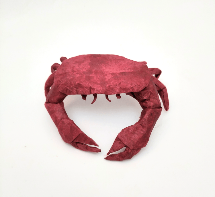
So when it came to designing a new crab, I knew it would be something of a landmark for me, reminding me of how far I’ve come. Which is my excuse for spending far too much time on it.
Extending Tree Theory
Tree Theory is fantastic for making stick figures, so it applies when designing slender and pointy subjects (e.g. insects, dragons, etc.), but it doesn’t help when you have to make wide flaps. I wanted to make a human figure with butterfly wings, and I knew I’d either need to use more of a trial-and-error approach or develop some new tools (having an actual subject as a goal is just about the only way I find the motivation to spend a lot of time developing origami theory). Naturally, I went for the latter.
So I spent a bit of time working on what I later called ‘Canopy Theory’ last year. The idea is to give a minimal amount of paper required to make flaps that are convex polygons (rather than just lines like in Tree Theory). I found out about Mu Tsun-Tsai’s ERM a few months later (see https://origami.abstreamace.com/2021/12/12/geography-of-origami-a-brief-introduction-to-the-edge-river-method/), which has some overlap with Canopy Theory, and I’m told others have come up with similar ideas too. So I’m a little hesitant to say I’ve done anything ‘new’, but I think we all have different approaches, and having new models which exemplify either the common ideas or individual slants is, perhaps, just as important. You can read about Canopy Theory and find instructions for Psyche in my upcoming book, Folding Fantasy: Volume 2. I’ve also submitted an adapted version of the text to 8OSME.
For nearly a year since coming up with the theory, I’d only designed one model using it. Part of the reason is that it lends itself more naturally to computer implementation (see TreeMaker: https://langorigami.com/article/treemaker/), but there isn’t any software that expands upon Tree Theory in the way I needed it to (that I’m aware of). Of course, Lang has made the source code for TreeMaker available which could be edited, but it’s more fun to write something yourself from scratch (and often easier too).
However, I’m only an amateur coder and I’m most familiar with GML (Game Maker Language), so that’s what I needed to use in order to make it a manageable project. If anyone wants it in a more common language, you’ll have to adapt it yourself…
Crabs
I’ll explain Canopy Theory indirectly by example. For the same of something concrete, let’s say we wanted to make a crab with just a few more details than the Nice Crab: as well as legs and claws, we’ll include antennae and eyes too. (If an image would help, use your favourite search engine to search for ‘brown crab’, which is a common crab species in Europe.) These features can all be well approximated by lines (we might want to watch out that the claw arms are not too thin, but rivers of large flaps tend to have plenty of spare width, so that shouldn’t be a problem).
The carapace
The issue is that the carapace (the crab’s shell) is not much like a line at all. The Nice Crab happened to have about enough paper to make a rough carapace shape by sneakily folding some of the paper for the claw arms at the correct angle. But it didn’t have enough paper to make a defined carapace which is separate from the other features.
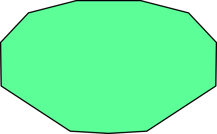
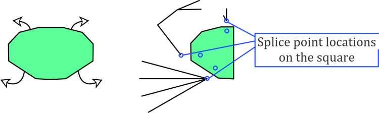
Let’s think about the paper required for the carapace. If we approximate it as a polygon, we get something like the shape below. To continue the existing flora-based terminology, I call this sort of shape a ‘crown’ (like the crown of a tree) since it is wide and is reminiscent of foliage. Hence the green colour.
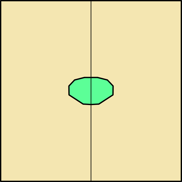
For a smooth carapace, we want this to be folded from one continuous region of the paper. Given the crease pattern of the Nice Crab as well as other origami crab designs, we can reasonably guess that the most efficient use of paper will have the carapace somewhere in the middle of the square rather than at an edge or a corner (and also that if we want a symmetric model, we’re better off with book symmetry than diagonal symmetry). This means the rim of the carapace will be a folded edge all the way around.
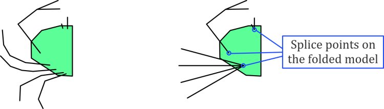
Splice points on the folded model
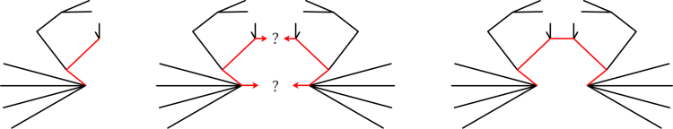
Let’s imagine what the folded model would look like when viewed from underneath. In fact, let’s more than imagine it: the claws, legs, etc. would come from roughly where shown on the left below. (I’m only using half a crab to save some time here, which is a usual origami design trick.) Then, to save ourselves some considerable work, let’s group similar features so there are only three locations from which features branch out. I call these locations splice points. This is on the right below.
We want to use the locations of the splice points to make some conditions which restrict how close various leaf nodes can become. This isn’t the sort of thing TreeMaker can do (as far as I know). Consider, for example, a stick figure that uses some of the splice points from the folded model to determine the length of some rivers which go between the splice points. This gives a cycle between this triangle of points, which means it isn’t a tree, and all the useful theory suddenly doesn’t apply any more. So this is the point where it becomes clear that we’ll need to make some new software.

We could make a tree by cutting one of the edges, as in the right image below. This is a good start but it doesn’t accurately give the distances between the antennae/eyes and the legs. This would result in a very inefficient model, and the problem compounds if we consider adding the right half of the model in this way – some of the points which are relatively close in the folded model would have to be separated by a large number of rivers with this basic approach.
To account for this, we need to be able to selectively reduce the length of various pairs of points. For the tree above, the biggest problem is between the pairs of legs on opposite sides of the crab. Thankfully, this is actually very easy to code since there’s already a distance condition on every pair of leaf nodes in a computer implementation of tree theory. Updating the number for this length is simply a matter of making sure we can identify any pair of nodes where this is relevant and lower the distance between them.

(Of course, I’m lazy, so in the code I’ve got at the moment, this updating is done manually by selecting a pair of nodes and pressing the down arrow several times, rather than using the actual location of the relevant branch nodes to calculate the correct distance automatically…)
Splice points on the square
From the top, the splice points cannot be seen. This is because the paper should wrap around the edge of the carapace and back underneath the rim to get to the splice points. So we can imagine unfolding the edge of the carapace to see where the splice points need to be – we reflect the previous splice points about the nearest edge of the carapace polygon.
In fact, we should consider reflecting each splice point on the folded model about multiple edges of the carapace polygon to get other splice point locations on the square. This is because several points on the square could collapse down to one point on the folded model, like branch points on a tree. This gives a whole splice region, but as this complicates the images, I’ll stick with what we have here.
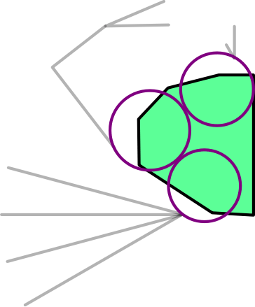
A proper approach would find a way to add the exact polygonal shape of the carapace. But we can use a cunning shortcut to approximate the result while still only using circles and rivers.
What we’ll do is add one new leaf node at each of the three splice points in the folded model. As long as the boundaries of these new leaf nodes end up at the splice point locations on the square, this will separate the features by the amount we need. The only new thing to code is locking these leaf nodes in position relative to each other, which is pretty simple.

There’s a bit of a gap between the upper circles though, which could cause a problem by letting some other features slip in closer than they ought to be. So let’s adjust the circles a little bit. (While we’re at it, we can make sure they don’t overlap, which doesn’t do anything meaningful besides looking nicer.)
How does it work?
So now it’s a case of letting the laptop crunch the numbers. Off it goes…
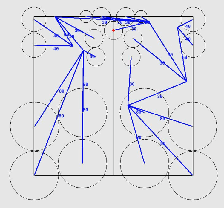
While it’s computing, let’s briefly look at how it find an arrangement. When two circles for leaf nodes get too close, a small acceleration is added to each circle so that they repel each other. It’s very simple, but it’s all that’s needed. Then you manually adjust the size of the square – make it smaller to squeeze the circles together and force them into an efficient arrangement. (Squeeze too much and you’ll necessarily have an overlap – increase the square size until this is no longer the case.) This approach could obviously be refined considerably, but it makes very good arrangements, which is all we set out to do.
This sort of approach is quite reliant on the starting locations of the circles – it can find locally optimal arrangements but not necessarily a global one (the same is true for TreeMaker). In general, verifying that an arrangement is globally optimal is a hard problem, and not even necessarily the goal. There are other design considerations such as flap thickness, colour changes, ease of folding, etc. that take higher priority. Manually moving around the circles to see what fits is the best compromise (and having a bit of agency is definitely a good thing).
I also added a small random motion to each circle for two reasons: Firstly, it’s a crude way of getting the computer to try a few random combinations so that it converges to an arrangement more quickly. Secondly, it stops multiple circles getting stuck along a raw edge forever because the random motion means one or other of them will try to push away from the edge.
TreeMaker is great, but I find it’s a bit static. It’s enjoyable watching the circles move around, and it’s illustrative to see the effect of moving a leaf node to a new position in the square in real time. As a reminder, take a look at the Instagram reel I posted showing it in action. However, please don’t go away thinking there’s now a better TreeMaker: besides adding one bit of functionality, everything else is significantly worse with what I’ve done – TreeMaker has everything from a better interface to the option to generate a crease pattern!
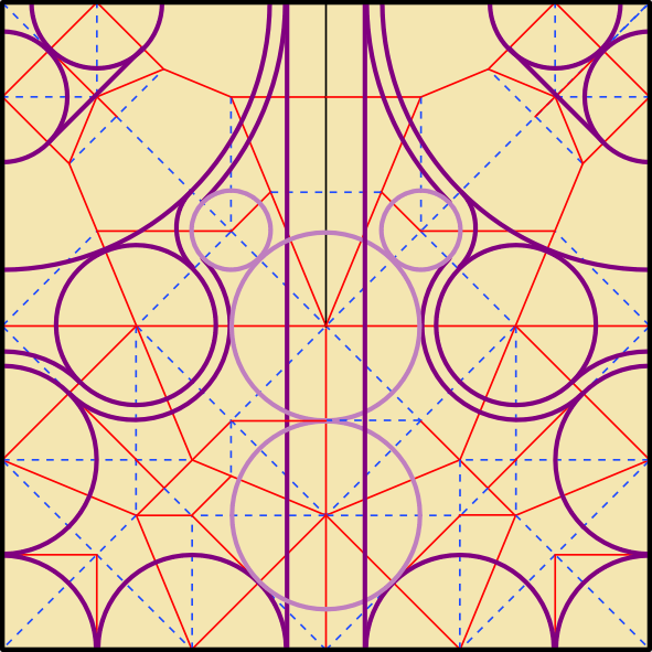
Final crease pattern
Speaking of, the crease pattern for the Brown Crab is below, with some references for the legs. I’ve overlaid a 16×16 grid to help locate some of the other features. Or at least, it’s a sort of crease pattern: it’s clearly not flat foldable, but it gives most of the structure you’d need to fold it yourself. This really is the only plan you’ll need before folding (it’s certainly the only one you’ll get!) – once the legs are precreased it’s essentially all shaping. (I’ve found that highly efficient designs are very good for this freeform shaping because the distances between flaps are exactly what they need to be.)
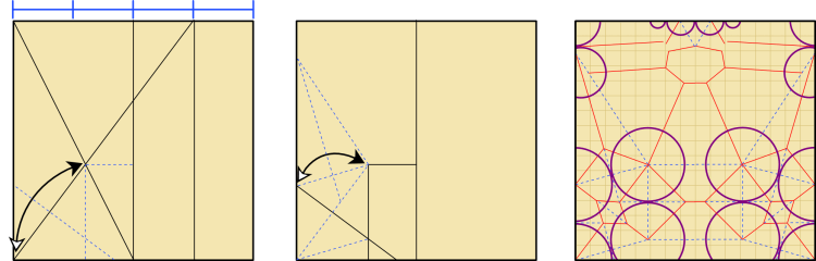
Comparing it to the Nice Crab crease pattern, we can see that the overall structures aren’t that different: the upper raw corners are used for claws, and the locations of the respective leg flaps are similar. But the Brown Crab has much less unused paper, which is how it finds space for the defined carapace, antennae, and eyes. Even without accounting for those extra features, the Brown Crab is about 8% more efficient than the Nice Crab (i.e. the Brown Crab ends up being around 8% larger if both models are folded from the same sheet of paper).
It’s a noticeable increase, but it takes much longer than 8% more time to fold the Brown Crab than the Nice Crab. I’ll let you decide if the effort is worth it.
Meta note
I could have easily fleshed out lots of details to make this post several times longer. But it felt plenty long already. Do let me know if you like seeing more technical aspects or if a snappier post is better!
Leave a Reply